CompleteAll projects
Patient-specific auxetic stents
A stent built on an auxetic lattice, so it conforms to irregular vessel geometry and spreads radial force instead of concentrating it.
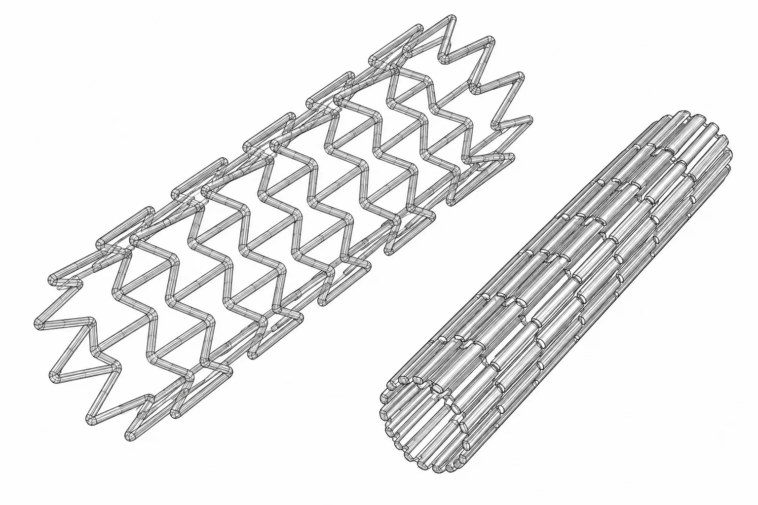
- Marked at centre left of the drawing.
- Marked at upper centre of the drawing.
- VARIABLE RADIAL FORCE, STENOTIC REGIONTODO: place on image
- FEA STRESS DISTRIBUTIONTODO: place on image
Description
What an auxetic is
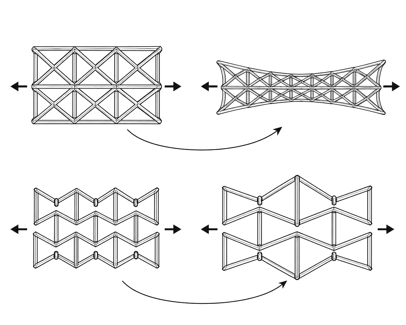
Stretch a rubber band and it gets thinner. Nearly everything does that: pull it one way and it narrows the other. An auxetic does the opposite: stretch it lengthwise and it widens. The behaviour comes from the shape of the lattice rather than the material it is cut from, so you get it by choosing a cell geometry.
On a stent that matters, because expanding the tube along its length also opens it outward. How much it opens is set cell by cell, by the width of each strut and the angle between struts, so a single stent can push hard where an artery is narrowed and barely at all where it is healthy.
Why a stent needs one
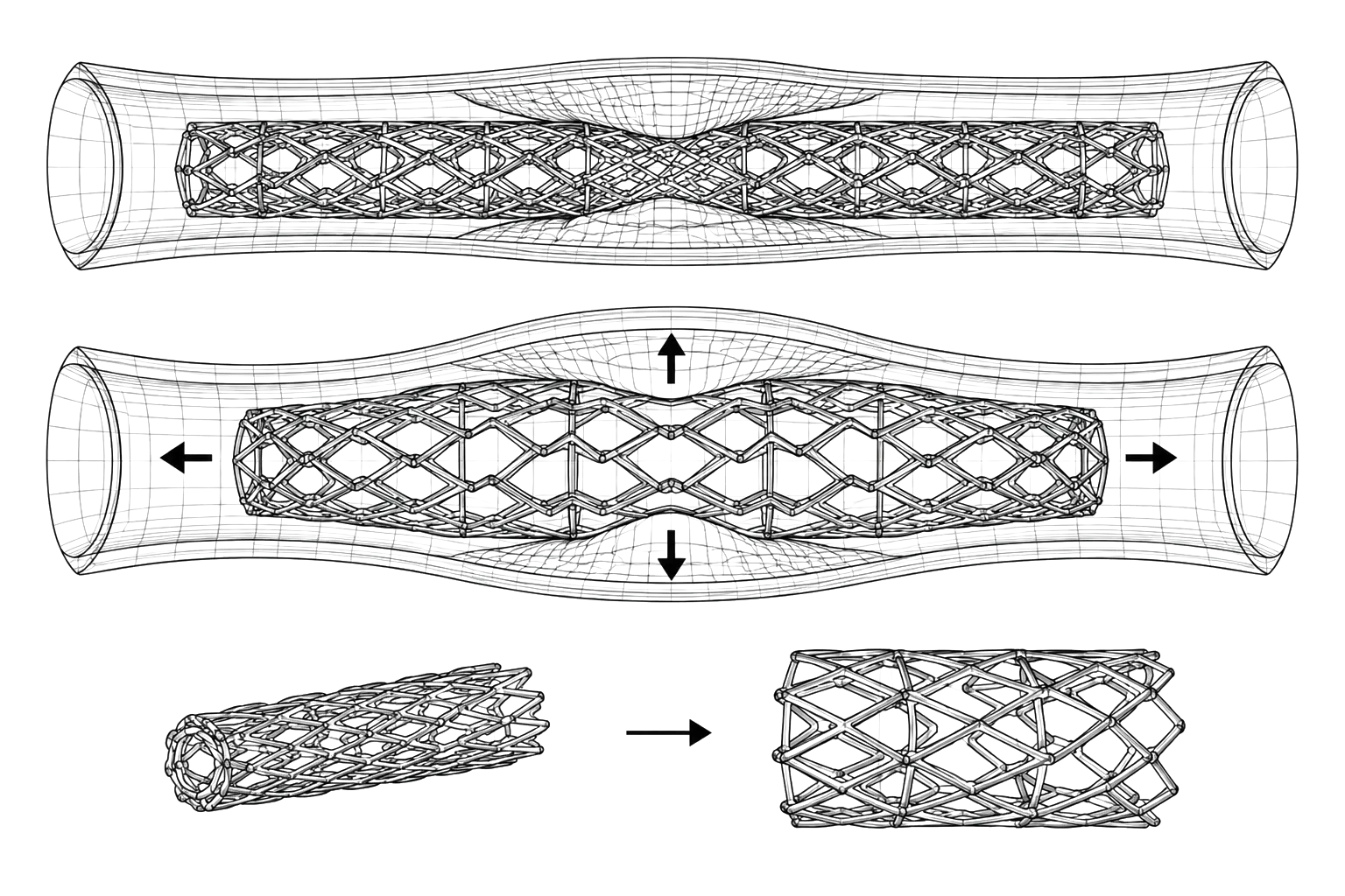
A stent is a mesh tube that props a blocked artery open. Conventional stents expand by the same amount along their whole length, and arteries are not the same along their whole length. Where the vessel is healthy the stent over-compresses it; where the blockage is worst it may not open far enough. Either way the force lands unevenly, and that mechanical injury to the vessel wall is one of the triggers for restenosis, the artery narrowing again after the stent goes in.
The lattice is also bi-stable: compliant hinges give it two stable shapes instead of one. It holds itself crimped for delivery through a catheter without being clamped, and holds itself open afterwards without being pushed.
How one gets built
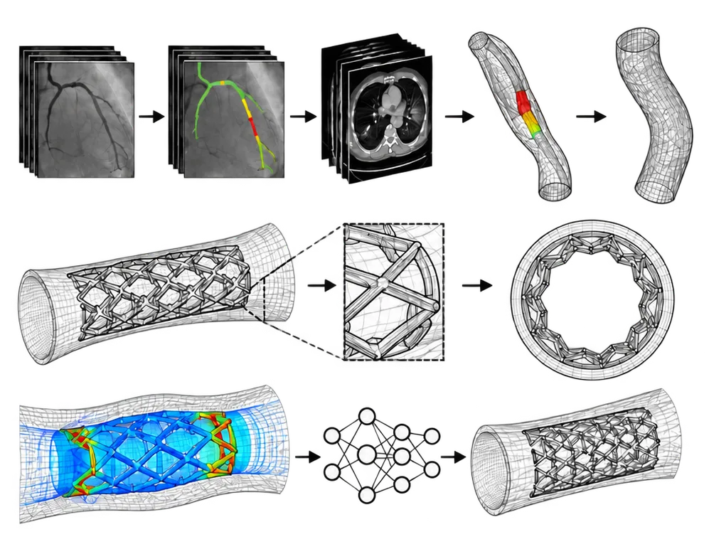
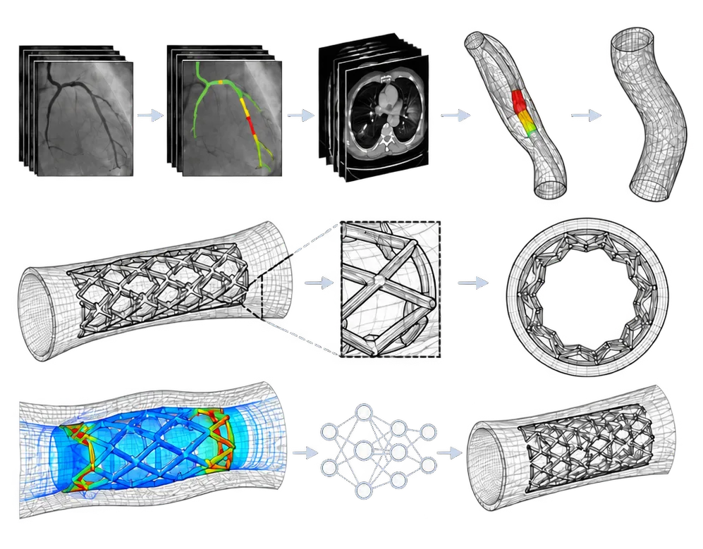
The geometry is fitted to the patient, from their own scans.
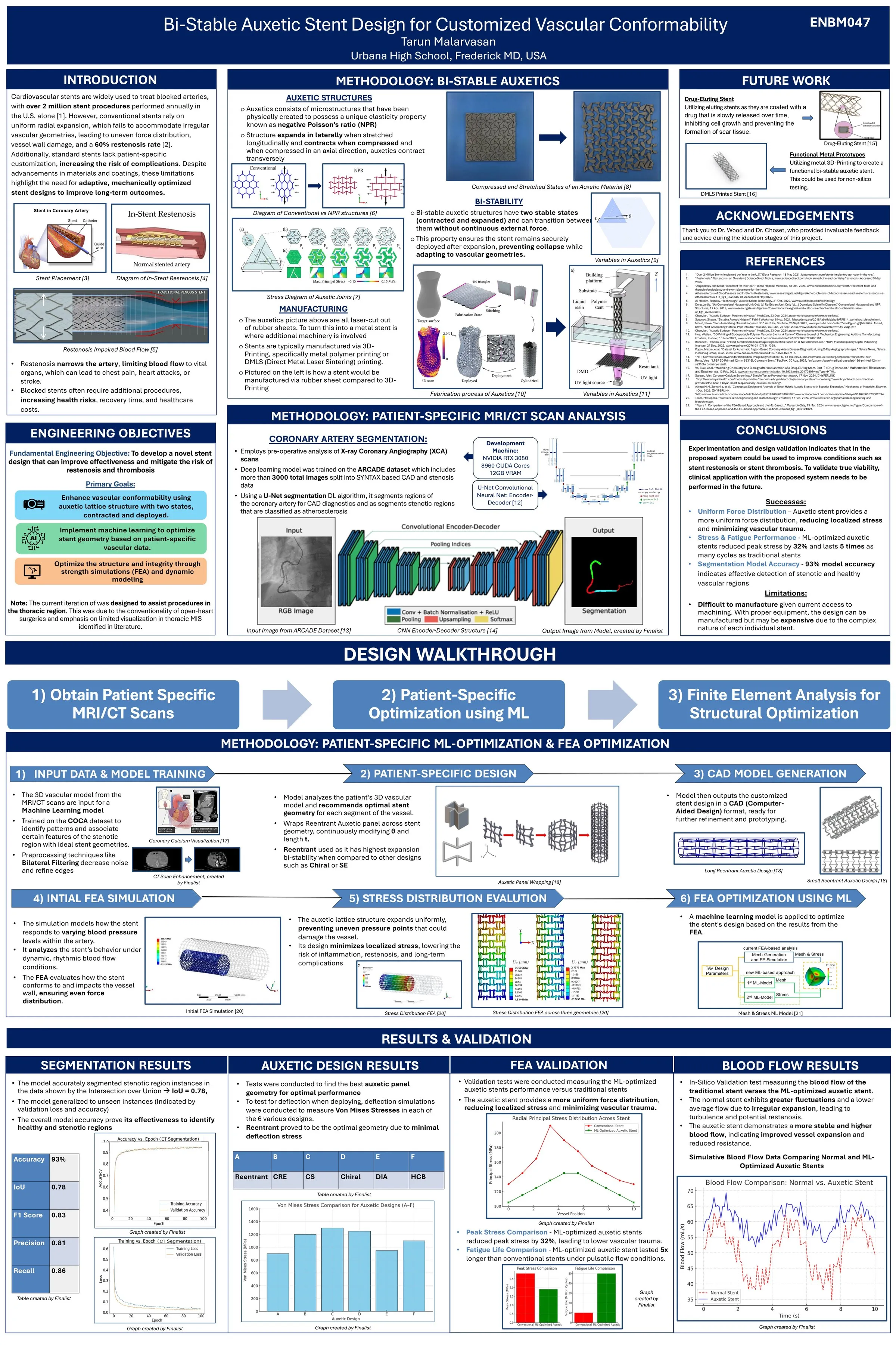
A U-Net convolutional network reads X-ray coronary angiograms and labels each pixel healthy, stenotic or thrombotic, so the narrowed stretch is located rather than estimated. A second, three-dimensional U-Net does the same on chest CT, and the flat coordinates from the first model are mapped onto the CT slices so the narrowing is placed in 3D. Those slices are aggregated into a volume, surfaced into a triangle mesh, smoothed, and exported as CAD.
The lattice is then wrapped onto that artery model, with each cell’s strut width and angle set from the local curvature and diameter. That is the step that turns a scan into a stent shaped for one person.
Finite element analysis checks the result: the artery modelled as hyperelastic tissue, the stent as superelastic nitinol, deployed virtually and then cycled under pulsatile flow. Running that by hand for every design is slow, so a graph neural network was trained on the simulation output, node positions in and von Mises stress out, to predict where a new mesh will concentrate stress and thicken those regions automatically.
What the simulations showed
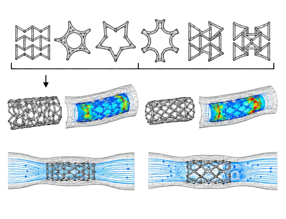
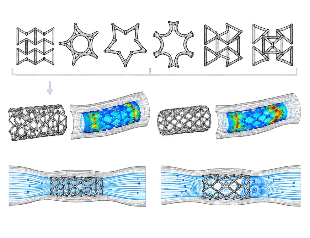
Six cell geometries were screened in three-point bending: re-entrant, trichiral, tetrachiral, hexachiral, tri-antichiral and tetra-antichiral. Re-entrant carried the lowest peak stress and was taken forward.
Against a conventional stent, the auxetic design held lower radial stress at every position along the vessel, and the drop in peak stress translated into roughly five times the predicted fatigue life. Blood-flow simulation over several cardiac cycles showed a higher and steadier flow rate, where the conventional stent produced fluctuation and local turbulence. That is what expanding evenly into a vessel that is not even will do.
Conclusion
Measured against a conventional stent in the same simulations:
Stress. Peak radial principal stress on the vessel wall came to about 150 MPa for the auxetic stent and over 220 MPa for the conventional one. Peak stress overall fell by 32%.
Fatigue. Predicted life was about 50 million cycles against 10 million, five times longer.
Flow. In ANSYS Fluent under pulsatile pressure, the auxetic stent gave a higher and steadier flow rate. The conventional stent’s uneven expansion caused more fluctuation and local turbulence.
Geometry. Of the six cell geometries tested in three-point bending, re-entrant had the lowest peak von Mises stress, so it was the one used.
Segmentation. The coronary artery model reached 93% validation accuracy, with an IoU of 0.78, F1 of 0.83, precision of 0.81 and recall of 0.86.
All of this is in silico. Inflammation and calcification were not modelled, and the optimiser can only be as good as the scans it was trained on. The next steps are bench testing on a pulsatile flow rig, then fabrication at clinical scale.
The project was sponsored by the Harvard Undergraduate OpenBio Laboratory and entered at ISEF as ENBM047. The full method and figures are in the publication linked above.